概要 
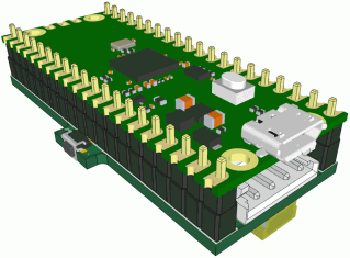
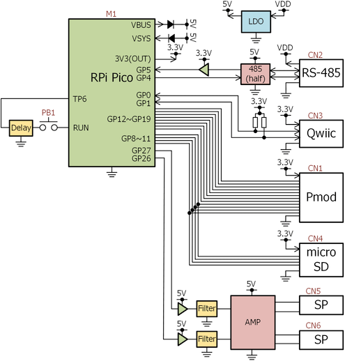
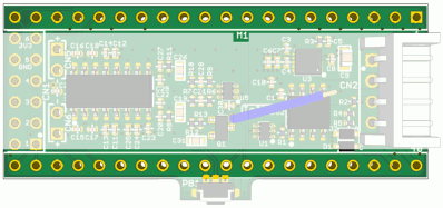
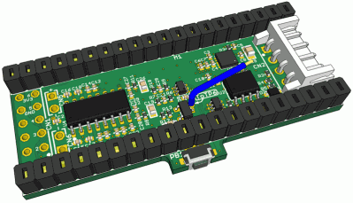
PicoSHIELDはRaspberry Pi Pico(以後Pico)にPmod・Qwiic・microSD・RS-485の各I/Fを増設するSHIELDです。
社内においてRP2040を適用する事例が増えてきた事と、お試し時のブレッドボードから脱却したいという思いから、よく知られたI/Fと極めて単純な回路のみで構成し、3Dプリンタで作ったケースに収めやすく小型なPico用SHIELDをデザインしました。
※本製品は半田付け作業を要求します。
※Picoは含まれません。
同梱内容 
| 型式等 | 数量 | 備考 |
| 本体 | 1 | E208 |
| 20ピンソケット | 2 | FSS-41035-20 |
| 20ピンヘッダ | 2 | PSS-410153-20 |
| 12ピンソケット | 1 | FSR-42057-06または相当品 |
基本仕様 
| 品番 | BTE110 | |
| PCBリビジョン | E208 (4層) | |
| 動作温度範囲 | -40~85℃ 結露なき事 | |
| 外形寸法 | 約51x23.5mm | |
| 重量 | ||
| 電源 | DC6~24V | CN2へ供給(Dynamixelが要求する電源) 絶対最大定格±50V |
| DC5V | CN2へ供給される電源からSHIELD上のLDOを介して生成 もしくはPicoのUSBバスパワー | |
| DC3.3V | SHIELDで生成されたDC5VないしUSBバスパワーからPico上のLDOを介して生成 | |
| コネクタ等 | JST S4B-EH x1 JST SM04B-SRSS-TB x1 microSDカードスロット x1 プッシュスイッチ x1 | |
M1 
- *の記述がある端子は基板内で使用されていたり、パーツの未実装により配線が完結していない事を意味する。詳細は()中のコメントと回路図を参照の事
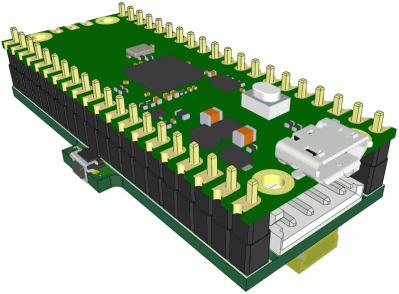
No. 端子名称 (Pico) No. 端子名称 (Pico) 1 *GP0(SDA0) 40 VBUS 2 *GP1(SCL0) 39 *VSYS 3 GND 38 GND 4 GP2 37 3V3_EN 5 GP3 36 *3V3(OUT) 6 *GP4(TXD1) 35 ADC_VREF 7 *GP5(RXD1) 34 GP28 8 GND 33 GND 9 GP6 32 *GP27(PWM5B) 10 GP7 31 *GP26(PWM5A) 11 *GP8 30 *RUN 12 *GP9 29 GP22 13 GND 28 GND 14 *GP10 27 GP21 15 *GP11 26 GP20 16 *GP12(GP19と短絡) 25 *GP19(GP12と短絡) 17 *GP13(GP15・GP16と短絡) 24 *GP18(GP14と短絡) 18 GND 23 GND 19 *GP14(GP18と短絡) 22 *GP17(CSn0) 20 *GP15(GP13・GP16と短絡) 21 *GP16(GP13・GP15と短絡) - 付属の低背ピンソケットを装着した場合
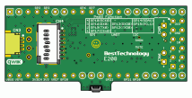
- Picoの装着位置と方向
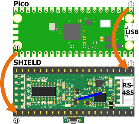
- 他のSHIELDやHATとの併用を想定していないが、使用端子や機能が競合しない場合はスタッキングヘッダを使用する事も可
- 装着前にジャンパ措置を行っておく必要がある
CN1 
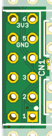
- 2.54mmピッチ2x6ピン
- ランド穴径 0.9mm
- 必要に応じてDigilent Pmodに対応したコネクタを装着可
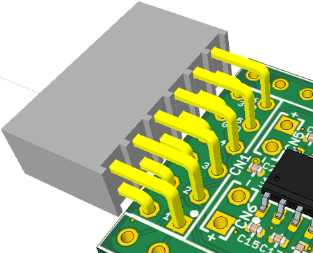
- 端子名 (端子番号はPmodの仕様に準拠)
No. 端子名称 (Pico) No. 端子名称 (Pico) 1 GP17(CSn0) 7 GP8 2 GP19(TX0) GP12(TXD0) 8 GP9 3 GP16(RX0) GP13(RXD0) GP15(SCL1) 9 GP10 4 GP18(SCK0) GP14(SDA1) 10 GP11 5 GND 11 GND 6 3.3V (OUT) 12 3.3V (OUT) - 各GPIOはDC3.3Vロジックレベル、5Vトレラント非対応
- 2~4ピンには各々複数のGPIOが短絡した状態で接続
- 7~9ピン(GP8~11)はCN4に並列に接続
CN2 
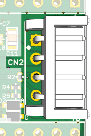
- RS-485 I/F
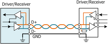
- 電源と通信用信号ラインが接続
Pats Name JST Parts Number 基板用ヘッダー B4B-EH, B4B-EH-A, S4B-EH ハウジング EHR-4 ターミナル SEH-00x 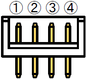
No. 信号名 1 GND 2 VDD (IN) 3 RS-485 D+ 4 RS-485 D- - Dynamixel I/Fに準拠したコネクタで、RS-485によるシリアル通信及びSHIELDへの電源供給を行う
- D+とD-間には120Ωのターミネータを装備済
- トランシーバの最大データレートは16Mbps
- 送信はGP4(TXD1)、受信はGP5(RXD1)を使用
CN3 
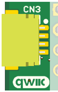
- SparkFun Qwiicに対応したコネクタ
- 電源と通信用信号ラインが接続
Pats Name JST Parts Number 基板用ヘッダー SM04B-SRSS-TB ハウジング SHR-04V-S ターミナル SSH-003T-P0.2-H
No. 端子名称 (Pico) 1 GND 2 3.3V (OUT) 3 GP0(SDA0) 4 GP1(SCL0) - 各GPIOはDC3.3Vロジックレベル、5Vトレラント非対応
- 3ピンと4ピンは2.2kΩの抵抗を介してDC3.3Vにプルアップ済
CN4 
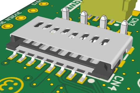
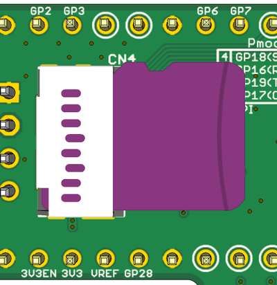
- microSDカードスロット
- 電源と4本の信号ラインが接続
Pats Name Molex Parts Number カードスロット 1051620001
NAME(TYPE) 端子名称 (Pico) P1(DAT2) - P2(CD/DAT3) GP9(CSn1) P3(CMD) GP11(TX1) P4(VDD) 3.3V P5(CLK) GP10(SCK1) P6(VSS) GND P7(DAT0) GP8(RX1) P8(DAT1) - P9(DET) - - GP8~GP11はCN1に並列に接続
- microSDカードを装着した状態
CN5, CN6 
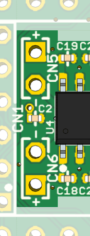
- 2.5mmピッチ2ピン
- ランド穴径 1mm
- スピーカ出力
- 端子名
No. 信号名 1 + Out 2 - Out - CN5はGP26(PWM5A)、CN6はGP27(PWM5B)の各々の端子から出力されるPWM信号を平滑しアンプを介して出力
- オーディオアンプは4~8Ωの数W程度のスピーカを直接駆動できるが、最大負荷時にDC5V電源の容量を超えるので、周波数は高めかつボリュームは控えめに。
- Hardware Design with RP2040が元ネタ
PB1 
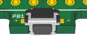
- シャポコさんの回路を踏襲し、PB1のクリックでリセット、長押しでUSBマスストレージを選択
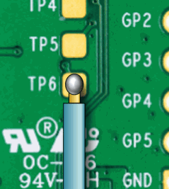
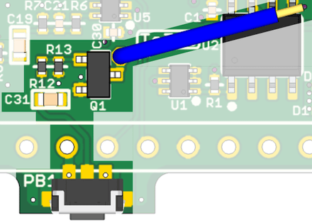
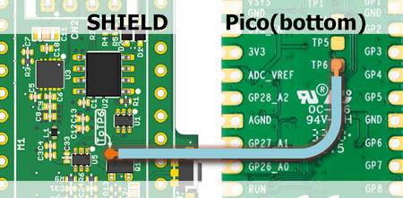
- PB1の信号はQ1を経由してToTP6ランドに接続、ランドにはジャンパ線が接続済
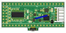
ジャンパ線のもう片方のリードをPico裏面のTP6へハンダ 最終的に次の図のようにジャンパで接続されていればOK
Picoの動作モード 
Picoは電源を印加した際のBOOTSELボタンの状態によって起動時の挙動が変わります。
SHIELDのジャンパ線がPicoのTP6へ正しく接続されていれば、BOOTSELボタンを使わずとも電源を印加したままPB1の押下時間のみでPicoのリセットとブートROMのUSBマスストレージへの遷移が行えます。
PB1をクリックするとPicoはリセット(書き込み済みのプログラムを再起動)、PB1を2秒程度長押しするとPicoはリセット後にUSBマスストレージとして機能します。
なおPB1周辺の回路の都合により、押下周期は数秒以上確保して下さい。
Arduino IDE 
後述するサンプルスケッチは、Arduino IDEにこちらのライブラリを適用しているものとします。PmodやQwiicに対応した既成のモジュールを使用する場合でも、大抵はArduino用のライブラリが用意されていますのですぐに試す事ができるでしょう。
なおRaspberry Pi Pico SDKの環境を自身で整える場合はこちらを参照下さい。
Digilent Pmod 
CN1はPmod互換コネクタとなっており、市販のPmodペリフェラルモジュールが接続できます(全てに対応するものではありません)。もちろん汎用のGPIOとしても使用できます。
SPI・UART・I2Cの3種類の異なるペリフェラルがアサインされているGPIOを、PmodのTypeと仕様に合わせてCN1へ接続しています。CN1-2・CN1-3・CN1-4には各々複数のGPIOが接続されいるため、電気的に競合しないようにGPIOやペリフェラルの初期化を行う必要があります。それ以外のCN1-1・CN1-5~12には単一のGPIOないし電源が接続されています。
なおCN1-7~10の信号はCN4にも並列に接続されているため、SHIELD上のmicroSDカードスロットとPmod I/Fを同時に使用する場合はCN1-7~10が外部回路に接続されないよう留意する必要があります。
正直なところPmodの互換性を担保している事よりも、競合させる必要の無い端子同士をつないでいるデメリットの方が大きいと思います。。。
Pmod Interface Type 2 (SPI) 
| No. | 端子名称 (Pico) | No. | 端子名称 (Pico) |
| 1 | GP17(CSn0) | 7 | GPIO8 |
| 2 | GP19(TX0) | 8 | GPIO9 |
| 3 | GP16(RX0) | 9 | GPIO10 |
| 4 | GP18(SCK0) | 10 | GPIO11 |
| 5 | GND | 11 | GND |
| 6 | 3.3V | 12 | 3.3V |
- 必要に応じてGPIOの内蔵プルアップないしプルダウンを活性化の事
#include <SPI.h>

void setup() {
  SPI.setCS(17);
  SPI.setTX(19);
  SPI.setRX(16);
  SPI.setSCK(18);
  SPI.begin();
}
Pmod Interface Type 3/3A (UART) 
| No. | 端子名称 (Pico) | No. | 端子名称 (Pico) |
| 1 | (CTS) | 7 | GPIO8 |
| 2 | GP12(TXD0) | 8 | GPIO9 |
| 3 | GP13(RXD0) | 9 | GPIO10 |
| 4 | (RTS) | 10 | GPIO11 |
| 5 | GND | 11 | GND |
| 6 | 3.3V | 12 | 3.3V |
- CTS・RTSにはペリフェラルとしてそれらに対応しないGPIOが接続されているが、必要に応じてSHIELD内で未使用のGP2(CTS0)とGP3(RTS0)を各端子にジャンパすれば対応可
void setup() {
  Serial1.setTX(12);
  Serial1.setRX(13);
  Serial1.begin(115200);
}
Pmod Interface Type 6/6A (I2C) 
| No. | 端子名称 (Pico) | No. | 端子名称 (Pico) |
| 1 | - | 7 | GPIO8 |
| 2 | - | 8 | GPIO9 |
| 3 | GP15(SCL1) | 9 | GPIO10 |
| 4 | GP14(SDA1) | 10 | GPIO11 |
| 5 | GND | 11 | GND |
| 6 | 3.3V | 12 | 3.3V |
- SCL・SDAにはDC3.3Vへのプルアップ抵抗を装備の事
#include <Wire.h>

void setup() {
  Wire1.setSCL(15);
  Wire1.setSDA(14);
  Wire1.begin();
}
SparkFun Qwiic 
CN3はQwiic互換コネクタとなっており、市販のQwiic対応モジュールが接続できます。
GPIOにはI2Cを前提としたプルアップ抵抗が装備されていますので、汎用のGPIOとして使用するのには向きません。
#include <Wire.h>

void setup() {
  Wire.setSDA(0);
  Wire.setSCL(1);
  Wire.begin();
}
microSDカード 
CN4はmicroSDカードスロットとなっています。
SDカードスロットにはPicoのSPI1の4本の信号線(GP8~11)と電源のみが接続され、他の端子は全てオープンです。またGP8~11はCN1-7~10と信号を共有していますので、CN1に装着したPmodペリフェラルモジュールと機能を競合させてはなりません。またSDカードの挿抜検出を行っていませんので、SDカードは常時挿入しておかなければなりません。
しかし数十MHzものクロック信号をピンヘッダを中継して延伸させている事の理不尽さは拭えきれません。
#include <Arduino.h>
#define SDFAT_FILE_TYPE 1
#include <SdFat.h>

#if SDFAT_FILE_TYPE == 0
SdFat sd;
//File dir;
//File file;
File32 dir;
File32 file;
#elif SDFAT_FILE_TYPE == 1
SdFat32 sd;
File32 dir;
File32 file;
#elif SDFAT_FILE_TYPE == 2
SdExFat sd;
ExFile dir;
ExFile file;
#elif SDFAT_FILE_TYPE == 3
SdFs sd;
FsFile dir;
FsFile file;
#else  // SD_FAT_TYPE
#error invalid SD_FAT_TYPE
#endif  // SD_FAT_TYPE

#define _SD_RX  (8)
#define _SD_CS  (9)
#define _SD_SCK (10)
#define _SD_TX  (11)

void setup() {
  Serial.begin();

  SPI1.setCS(_SD_CS);
  SPI1.setTX(_SD_TX);
  SPI1.setRX(_SD_RX);
  SPI1.setSCK(_SD_SCK);
  gpio_pull_up(_SD_RX);
  if (!sd.begin(SdSpiConfig(_SD_CS, 0, SD_SCK_MHZ(25), &SPI1))) {
    Serial.println("SD card error!");
    sd.initErrorHalt(&Serial);
  }
}

void loop () {
  String s;
  int d;
  static int n = 0;
  if (Serial.available()) {
    switch (Serial.read()) {
      case 'l':
        sd.ls("/", LS_R);
        break;
      case 'o':
        if (file.isOpen()) file.close();
        if (!file.open("test.txt", O_RDWR | O_CREAT | O_AT_END)) {
          Serial.println(">open ng");
        } else
          Serial.println(">open ok");
        break;
      case 'c':
        Serial.println (">close a file");
        if (file.isOpen()) file.close();
        break;
      case 'w':
        if (file.isOpen()) {
          file.seekEnd(0);
          s = "Write value = " + String(n++);
          if (file.println(s) > 0) Serial.println (">write ok"); else Serial.println (">write ng");
        } else
          Serial.println (">file is not open");
        break;
      case 'r':
        if (file.isOpen()) {
          file.seekSet(0);
          while ((d = file.read()) >= 0) Serial.write(d);
        } else
          Serial.println (">file is not open");
        break;
    }
  }
}
オーディオアンプ 
出力の一環として音もありという事で、CN5・CN6はスピーカ出力端子となっています。
PicoはDACを持たないためPWM信号を平滑した上でアンプに入力していますが、PWMキャリア周波数が低いと平滑時のリプルが大きくなり、無音であってもそこそこ電流が流れます。
他の機能を装備した段階でスカスカだったのでIMUかオーディオアンプどちらを載せようかと思案した結果オーディオアンプを選択したのですが、実装面積の大半を占めているにもかかわらず彼方此方のノイズが載ったりと微妙です。
ある程度マトモに試聴するのであれば、CN2に外部電源を供給して下さい。USBバスパワーではノイズで耳を痛めます。
#include <PWMAudio.h>
#include <pico/bootrom.h>

#define INCBIN(file, sym) __asm(\
   ".section .rodata\n"                  \
   ".balign 4\n"                         \
   ".global " #sym "\n"                  \
   #sym ":\n"                            \
   ".incbin \"" file "\"\n"              \
   ".global _size_" #sym "\n"            \
   ".set _size_" #sym ", . - " #sym "\n" \
   ".balign 4\n"                         \
   ".section \".text\"\n");              \
   extern const void *sym;\
   extern const size_t *_size_##sym;

#define _AUDIO_PWM_L  (26)
#define _AUDIO_PWM_R  (27)

PWMAudio pwm(_AUDIO_PWM_L);

template < typename typ, std::size_t size > size_t GetNumOfElems (const typ (&array)[size]) { return size; }

// Direct import of signed 8-bit RAW files (11.025kHz)
// Specify file name by absolute path
INCBIN ("./raw1.raw", pcm_raw1);
INCBIN ("./raw2.raw", pcm_raw2);

// Set various conditions for imported PCM data
struct TPCMInfo {
  int8_t  *raw; // PCM data pointer
  int32_t size; // PCM data byte size
  int8_t  byte; // 1=8bit, 2=16bit
  int32_t ind;  // -1:stop, 0:start
  int16_t freq; // 256:no conversion
  uint8_t vol;  // 127:max volume
} PCMInfo[] {
  { (int8_t *)&pcm_raw1, (int)&_size_pcm_raw1, 1, -1, 256, 127 },
  { (int8_t *)&pcm_raw2, (int)&_size_pcm_raw2, 1, -1, 256, 127 },
};

// Playback of PCM data (including volume and frequency conversion)
struct CPCM {
  // Process frequency and volume
  void Mix (int16_t *v) {
    int32_t vv = *v;
    for (uint8_t i = 0; i < GetNumOfElems (PCMInfo); i++) {
      if (PCMInfo[i].ind >= 0) {
        PCMInfo[i].ind += PCMInfo[i].freq;
        if ((PCMInfo[i].ind >> 8) >= PCMInfo[i].size) PCMInfo[i].ind = -1;
        else vv += (((PCMInfo[i].raw[PCMInfo[i].ind >> 8]) << 2) * PCMInfo[i].vol) >> 7;
      }
    }
    *v = MIN(MAX(vv, SHRT_MIN), SHRT_MAX);
  }

  // Excitation of PCM reproduction (playback is performed by MRT and DAC)
  void Start (uint8_t ind, uint8_t tone, uint8_t vol) {
    const uint16_t pcm_tone_table[12] = {8192,8679,9195,9742,10321,10935,11585,12274,13004,13777,14596,15464};  // oct=9
    if ((ind < GetNumOfElems (PCMInfo)) && (tone <= 127)) {
      div_t o_t = div (tone, 12);
      PCMInfo[ind].ind = -1;
      PCMInfo[ind].freq = pcm_tone_table[o_t.rem] >> (9 - o_t.quot);
      PCMInfo[ind].vol = vol;
      PCMInfo[ind].ind = 0;
    }
  }

  void Stop (uint8_t ind) {
    if (ind < GetNumOfElems (PCMInfo) - 1) PCMInfo[ind].ind = -1;
  }
} PCM;

// Called on completion of DMA buffer transfer for PWM audio
void tran_cb() {
  static uint8_t updcyc = 0;
  static int16_t v = 0;
  while (pwm.availableForWrite()) {
    // The PWM carrier frequency is assumed to be 220.5 kHz, while the audio data is assumed to be 44.1 kHz at maximum.
    // Therefore, the same data must be maintained for 5 samples.
    // Since PCM assumes even lower frequency and lower resolution data, conversion is necessary when storing the data in the buffer.
    if (updcyc++==0) {
      v = 0;
      PCM.Mix(&v);
    }
    updcyc %= 5;
    pwm.write(v << 6);
  }
}

void setup() {
  // Initialize PWM Audio Library
  pwm.onTransmit(tran_cb);
  // If the carrier frequency of the PWM is low, the smoothing filter does not play its role.
  // Here, the frequency was determined experimentally by observing the heat generation and current conditions.
  pwm.begin(220500);

  delay (500);
  Serial.begin();
}

void loop() {
  while (1) {
    if (Serial.available()) {
      switch (Serial.read()) {
        case '!': reset_usb_boot(0, 0); break;
        // The PC keyboard is used as a piano keyboard to play PCM 0 data.
        case 'z': PCM.Start (0, 24 + 0, 127); break;
        case 's': PCM.Start (0, 24 + 1, 127); break;
        case 'x': PCM.Start (0, 24 + 2, 127); break;
        case 'd': PCM.Start (0, 24 + 3, 127); break;
        case 'c': PCM.Start (0, 24 + 4, 127); break;
        case 'v': PCM.Start (0, 24 + 5, 127); break;
        case 'g': PCM.Start (0, 24 + 6, 127); break;
        case 'b': PCM.Start (0, 24 + 7, 127); break;
        case 'h': PCM.Start (0, 24 + 8, 127); break;
        case 'n': PCM.Start (0, 24 + 9, 127); break;
        case 'j': PCM.Start (0, 24 + 10, 127); break;
        case 'm': PCM.Start (0, 24 + 11, 127); break;
        case ',': PCM.Start (0, 24 + 12, 127); break;

        case 'q': PCM.Start (0, 24 + 0, 127); break;
        case 'w': PCM.Start (1, 24 + 0, 127); break;
      }
    }
  }
}
RS-485 I/F 
CN2は電源の入力とRS-485 I/F端子となっており、RS-485 I/Fを装備したDynamixel Xシリーズとの接続を想定しています。
Dynamixelと通信する場合の接続例です。
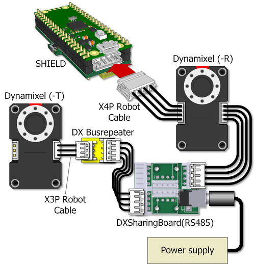
ここでは便宜的にDXSharingBoardを使用していますが、この構成が必須ではありませんし、SHIELDをDynamixelのコネクタに直結させなければならないという事でもありません。
またTTL I/F版のDynamixelの場合は、DX Busrepeaterを挿入してI/Fを変換する必要があります。
Dynamixelと電源をつないだだけで何かしてくれるものではありませんので、専用のパケットを用いた通信を行うプログラムを適宜作成する必要があります。Arduino IDEを使用しているのであれば、DXSHIELD向けに提供しているDynamixel Library for ArduinoのV1.6以降が使用できます。まずはDXLIBが要求する通信用関数を準備します。
// The new DXLIB no longer includes the processing for serial communication to increase versatility,
// so it is necessary to write that part in its own sketch.
#pragma once
#include <Arduino.h>

#define _RS485_TX (4)
#define _RS485_RX (5)

// Init
uint32_t us_init(uint32_t baud) {
  Serial2.setRX(_RS485_RX);
  Serial2.setTX(_RS485_TX);
  Serial2.setFIFOSize(512);
  Serial2.begin(baud);
  Serial2.setTimeout(20);
  return baud;
}

// Deinit
void us_deinit(void) {
  Serial2.end();
}

// Set baudrate
uint32_t us_setbaudrate(uint32_t baud) {
  us_deinit();
  return us_init(baud);
}

// Clear receive buffer
void us_rxpurge(void) {
  while (Serial2.available()) Serial2.read();
}

// Send 1 byte
void us_putc(uint8_t c) {
  Serial2.write(c);
}

// Send multiple bytes
void us_puts(const uint8_t *buf, int len) {
  Serial2.write(buf, len);
}

// Received multiple bytes
int us_gets(uint8_t *buf, int len) {
  if (len == 0) return 0;
  return Serial2.readBytes(buf, len);
}

// Flush transmit buffer
void us_flush(void) {
  Serial2.flush();
}
具体的にDynamixelを動かすプログラムを作成してみます。以下は出荷時デフォルトのXM430-W350-Rを対象とし、起動時に位置指令が可能な範囲と現在位置を取得し、それを元にホーンを往復運動させるスケッチです。
#include <dx2lib.h>
#include <dx2memmap.h>
#include "dxif.h"
#define TARGET_ID (1)
#define BAUDRATE (57600)
DX2LIB::TDXHost_ConfParam param {
us_init, us_deinit, us_setbaudrate, us_rxpurge, us_putc, us_puts, us_gets, us_flush
};
// Create dx2
DX2LIB dx2 (¶m);
int32_t maxpos, minpos, gpos = 0;
void setup() {
dx2.begin (BAUDRATE);
// Get the range for position control
dx2.ReadLongData (TARGET_ID, ADDRESS_X_MAX_POSITION_LIMIT, (uint32_t *)&maxpos, NULL);
dx2.ReadLongData (TARGET_ID, ADDRESS_X_MIN_POSITION_LIMIT, (uint32_t *)&minpos, NULL);
// Start control
dx2.WriteByteData (TARGET_ID, ADDRESS_X_TORQUE_ENABLE, 1, NULL);
// Obtain the current position and use it as the initial value for the goal position.
dx2.ReadLongData (TARGET_ID, ADDRESS_X_PRESENT_POSITION, (uint32_t *)&gpos, NULL);
}
void loop() {
static int32_t dir = 30;
// Move the position back and forth through the full range of positions.
gpos += dir;
if (gpos >= maxpos) {
gpos = maxpos;
dir *= -1;
} else if (gpos <= minpos) {
gpos = minpos;
dir *= -1;
};
// Set goal position
dx2.WriteLongData (TARGET_ID, ADDRESS_X_GOAL_POSITION, gpos, NULL);
delay (10);
}
DXLIB v1.6から追加されたAPIやFreeRTOSを使用すると、Dynamixelのモデルに依存する事無く煩雑なシーケンスや複数軸の同期処理を少ないコード量で処理できます。
複数軸の角度を時間に応じて遷移させるモーションを再生するスケッチを以下に紹介しておきます(Drive ModeでTime-base Profileが選択できるモデル限定)。
#include <FreeRTOS.h>
#include <Adafruit_TinyUSB.h>
#include <task.h>
#include <timers.h>
#include <semphr.h>
#include <vector>
#include <stdio.h>
#include <stdarg.h>
#include "src/dx2lib.h"
#include "dxif.h"
#define BAUDRATE (3000000)
#define MAX_AXISNUM 32
int printff(const char *format, ...) {
static char buf[200];
va_list args;
va_start(args, format);
int result = vsnprintf(buf, sizeof(buf), format, args);
va_end(args);
Serial.print(buf);
Serial.flush();
return result;
}
//-----------------------------------------------
// Motion class
//-----------------------------------------------
class DXLMotion {
public:
typedef struct {
uint8_t id;
uint8_t op_mode;
uint8_t drive_mode;
} TTServoInfo;
typedef std::vector<TTServoInfo> TServoInfo;
typedef double TPose[MAX_AXISNUM];
typedef struct {
TPose angles;
double sec;
} TTMotion;
typedef struct {
const std::vector<uint8_t> ids;
const std::vector<TTMotion> motion;
} TMotion;
uint32_t actualbaud;
DX2LIB *dx2lib;
void begin(uint32_t baud) {
if (!initialized) {
anchor = this;
dx2lib = new DX2LIB((DX2LIB::PDXHost_ConfParam)¶m);
dx2lib->begin(baud);
xMutex = xSemaphoreCreateMutex();
dx2lib->SemLock = _slock;
dx2lib->SemFree = _sfree;
MotionTimer = xTimerCreate("Timer", pdMS_TO_TICKS(1000), pdFALSE, anchor, _MotionTimerCB);
xTimerStop(MotionTimer, 0);
initialized = true;
}
}
void end(void) {
if (!initialized) {
// vTaskDelete (task_mon_handler);
xTimerDelete(MotionTimer, 0);
dx2lib->end();
dx2lib->SemLock = nullptr;
dx2lib->SemFree = nullptr;
delete dx2lib;
initialized = false;
anchor = nullptr;
}
}
bool init_servo(const TServoInfo *sinfo) {
if (!initialized) return false;
detect_ids.clear();
dx2lib->InitDevicesList();
Serial2.setTimeout(10);
for (const auto &info : *sinfo)
if (dx2lib->GetModelInfo(info.id)->devtype != devtNONE) detect_ids.push_back(info.id);
bool result = (detect_ids.size() == sinfo->size());
Serial2.setTimeout(50);
if (detect_ids.size() > 0) {
for (const auto &info : *sinfo) {
if (dx2lib->Reboot(info.id)) {
// When dynamically switching modes of operation, we don't want previously set volatile parameters to remain, so we encourage a reboot.
for (int i=0;i<20 && !dx2lib->Ping(info.id);i++) ;
if (dx2lib->SetOperatingMode(info.id, info.op_mode)) {
if (dx2lib->SetDriveMode(info.id, info.drive_mode)) {
} else result = false;
} else result = false;
} else result = false;
}
} else result = false;
return result;
}
bool play(const TMotion *motion) {
if (!initialized) return false;
//bool DXLMotion::play(const std::vector<uint8_t> *target_ids, const std::vector<TMotion> *motion) {
if (detect_ids.size() == 0) return false;
xTimerStop(MotionTimer, 0);
motionind = 0;
SpecMotion = (TMotion *)(void *)motion;
if (dx2lib->SetMultipleGoalValues(SpecMotion->ids.data(), &SpecMotion->motion[motionind].angles[0], SpecMotion->ids.size(), SpecMotion->motion[motionind].sec)) {
xTimerChangePeriod(MotionTimer, pdMS_TO_TICKS(SpecMotion->motion[motionind].sec * 1000), portMAX_DELAY);
return (xTimerStart(MotionTimer, portMAX_DELAY) == pdPASS);
}
return false;
}
bool stop(const std::vector<uint8_t> *target_ids) {
if (!initialized) return false;
if (detect_ids.size() == 0) return false;
xTimerStop(MotionTimer, 0);
motionind = 0;
return dx2lib->StandStillAngles(target_ids->data(), target_ids->size());
}
bool set_gate(const std::vector<uint8_t> *target_ids, bool en) {
if (!initialized) return false;
return dx2lib->SetTorqueEnablesEquival(target_ids->data(), target_ids->size(), en);
}
bool get_angle(const std::vector<uint8_t> *target_ids, std::vector<double> *pangle) {
if (!initialized) return false;
return dx2lib->GetPresentAngles(target_ids->data(), pangle->data(), target_ids->size());
}
bool get_velocity(const std::vector<uint8_t> *target_ids, std::vector<double> *pvelo) {
if (!initialized) return false;
return dx2lib->GetPresentVelocities(target_ids->data(), pvelo->data(), target_ids->size());
}
bool get_current(const std::vector<uint8_t> *target_ids, std::vector<double> *pcur) {
if (!initialized) return false;
return dx2lib->GetPresentCurrents(target_ids->data(), pcur->data(), target_ids->size());
}
private:
static DXLMotion *anchor;
bool initialized = false;
std::vector<uint8_t> detect_ids;
// Motion data structure
TMotion *SpecMotion;
int motionind;
SemaphoreHandle_t xMutex = nullptr;
TimerHandle_t MotionTimer = nullptr;
xTaskHandle task_mon_handler;
static uint32_t _us_init(uint32_t baud) { return us_init(baud); };
static void _us_deinit(void) { us_deinit(); };
static uint32_t _us_setbaudrate(uint32_t baud) { return us_setbaudrate(baud); };
static void _us_rxpurge(void) { us_rxpurge(); };
static void _us_putc(uint8_t c) { us_putc(c); };
static void _us_puts(const uint8_t *buf, int len) { us_puts(buf, len); };
static int _us_gets(uint8_t *buf, int len) { return us_gets(buf,len); };
static void _us_flush(void) { us_flush(); };
const DX2LIB::TDXHost_ConfParam param = { _us_init, _us_deinit, _us_setbaudrate, _us_rxpurge, _us_putc, _us_puts, _us_gets, _us_flush };
void slock(void) {
xSemaphoreTake(xMutex, portMAX_DELAY);
}
void sfree(void) {
xSemaphoreGive(xMutex);
}
static void _slock(void) { anchor->slock(); };
static void _sfree(void) { anchor->sfree(); };
void MotionTimerCB(TimerHandle_t xTimer) {
xTimerStop(MotionTimer, 0);
if (++motionind < SpecMotion->motion.size()) {
dx2lib->SetMultipleGoalValues(SpecMotion->ids.data(), &SpecMotion->motion[motionind].angles[0], SpecMotion->ids.size(), SpecMotion->motion[motionind].sec);
xTimerChangePeriod(MotionTimer, pdMS_TO_TICKS(SpecMotion->motion[motionind].sec * 1000), portMAX_DELAY);
}
}
static void _MotionTimerCB(TimerHandle_t xTimer) { anchor->MotionTimerCB(xTimer); }
void task_mon();
} motion;
DXLMotion *DXLMotion::anchor = nullptr;
//-----------------------------------------------
// Motion data
//-----------------------------------------------
const std::vector<uint8_t> my_id_list {1,2,3,4,5,6,7,8};
const DXLMotion::TServoInfo servo_info = { {1,1,0x4}, {2,4,0x4}, {3,4,0x4}, {4,4,0x4}, {5,4,0x4}, {6,4,0x4}, {7,4,0x4}, {8,4,0x4} };
const DXLMotion::TMotion motion1 = {
my_id_list,
{ { { 0, 0, 0, 0, 0, 0, 0, 0 }, 1.0 } }
};
const DXLMotion::TMotion motion2 = {
my_id_list,
{ { { 90, 90, 90, 90, 90, 90, 90, 90 }, 1.0 } }
};
const DXLMotion::TMotion motion3 = {
my_id_list,
{ { { -90, -90, -90, -90, -90, -90, -90, -90 }, 1.0 } }
};
const DXLMotion::TMotion motion4 = {
my_id_list,
{ { { 180, 180, 180, 180, 180, 180, 180, 180 }, 1.0 } }
};
const DXLMotion::TMotion motion5 = {
my_id_list,
{ { { -180, -180, -180, -180, -180, -180, -180, -180 }, 1.0 } }
};
const DXLMotion::TMotion motion6 = {
my_id_list,
{{ { -30, -30, -30, -30, -30, -30, -30, -30 }, 0.2 },
{ { 30, 30, 30, 30, 30, 30, 30, 30 }, 0.2 },
{ { -30, -30, -30, -30, -30, -30, -30, -30 }, 0.2 },
{ { 30, 30, 30, 30, 30, 30, 30, 30 }, 0.2 },
{ { -30, -30, -30, -30, -30, -30, -30, -30 }, 0.2 },
{ { 30, 30, 30, 30, 30, 30, 30, 30 }, 0.2 },
{ { -30, -30, -30, -30, -30, -30, -30, -30 }, 0.2 },
{ { 30, 30, 30, 30, 30, 30, 30, 30 }, 0.2 }
}
};
const DXLMotion::TMotion motion7 = {
my_id_list,
{ { { -45, 45, -45, 45, -45, 45, -45, 45 }, 2.0 },
{ { 90, 90, 90, 90, 90, 90, 90, 90 }, 2.0 },
{ { -30, -30, -30, -30, -30, -30, -30, -30 }, 2.0 },
{ { -180, -180, -180, -180, -180, -180, -180, -180 }, 2.0 }
}
};
const DXLMotion::TMotion motion8 = {
my_id_list,
{ { { 0, 0, 0, 0, 0, 0, 0, 0 }, 1.0 } }
};
const DXLMotion::TMotion motion9 = {
my_id_list,
{ { { 0, 0, 0, 0, 0, 0, 0, 0 }, 1.0 } }
};
const DXLMotion::TMotion motion10 = {
my_id_list,
{ { { 0, 0, 0, 0, 0, 0, 0, 0 }, 1.0 } }
};
const DXLMotion::TMotion motion11 = {
my_id_list,
{ { { 0, 0, 0, 0, 0, 0, 0, 0 }, 1.0 } }
};
const std::vector<const DXLMotion::TMotion *> mlist {
&motion1, &motion2, &motion3, &motion4, &motion5, &motion6, &motion7, &motion8, &motion9, &motion10, &motion11
};
void setup() {
motion.begin(BAUDRATE);
}
void loop() {
int n;
char c;
while (1) {
while (Serial.available()) {
switch (c = Serial.read()) {
case 'S':
printff("start scan\n");
motion.init_servo(&servo_info);
motion.dx2lib->PrintDevicesList(&printff);
motion.set_gate(&my_id_list, true);
break;
case 'a' ... 'k':
n = c - 'a';
motion.play(mlist[n]);
break;
}
}
}
delay(100);
}
次のようなスケッチを使うと、PicoのUSBとSHIELDのRS-485をブリッジするI/Fとして機能させる事ができます。Dynamixelの設定を変更する際に別途USBシリアルI/Fの類いを用意する必要が無いので便利です。なお予めArduino IDEでUSB StackをAdafruit Tiny USBに変更した上でコンパイルして下さい。
#include <Adafruit_TinyUSB.h>

#define _RS485_TX (4)
#define _RS485_RX (5)

uint32_t prevbaud;
uint8_t b_usb[4096], b_uart[4096];

void setup() {
  uint32_t baud = 115200;
  pinMode (LED_BUILTIN, OUTPUT);
  Serial.begin (baud);

  Serial2.setFIFOSize (4096);
  Serial2.setRX (_RS485_RX);
  Serial2.setTX (_RS485_TX);
  Serial2.begin (baud);
}

void loop() {
  uint32_t l;

  if ((l = Serial.available()) > 0) {
    if (l > sizeof(b_usb)) l = sizeof(b_usb);
    digitalWrite (LED_BUILTIN, 1);
    Serial.readBytes (b_usb, l);
    Serial2.write (b_usb, l);
    digitalWrite (LED_BUILTIN, 0);
  }
  if (Serial2.available() > 0) {
    digitalWrite (LED_BUILTIN, 1);
    while (Serial2.available() > 0) {
      uint8_t d = Serial2.read ();
      Serial.write (d);
    }
    digitalWrite (LED_BUILTIN, 0);
  }
  if (Serial.baud() != prevbaud) {
    Serial2.end();
    prevbaud = Serial.baud();
    Serial2.begin (prevbaud);
  }
}
なおAdafruit Tiny USBはRTS/CTSのフロー制御が必須なコードになっているため、ハードフローがONになっていないツール(DYNAMIXEL Wizard 2.0等)では先のスケッチを用いても通信ができません。暫定的ではありますが、Arduino IDEに適用したパッケージの「libraries/Adafruit_TinyUSB_Arduino/src/class/cdc/cdc_device.c」に次のようなパッチを当てればハードフローなしのアプリケーションであっても通信ができるようになります。
--- cdc_device.c.org
+++ cdc_device.c
@@ -113,7 +113,7 @@
 bool tud_cdc_n_connected(uint8_t itf)
 {
   // DTR (bit 0) active  is considered as connected
-  return tud_ready() && tu_bit_test(_cdcd_itf[itf].line_state, 0);
+  return true;
 }

 uint8_t tud_cdc_n_get_line_state (uint8_t itf)
@@ -388,7 +388,7 @@
         p_cdc->line_state = (uint8_t) request->wValue;

         // Disable fifo overwriting if DTR bit is set
-        tu_fifo_set_overwritable(&p_cdc->tx_ff, !dtr);
+//        tu_fifo_set_overwritable(&p_cdc->tx_ff, !dtr);

         TU_LOG2("  Set Control Line State: DTR = %d, RTS = %d\r\n", dtr, rts);
デモ 
こちらのページにて具体的な用途別のプログラムを紹介しています。
注意事項 
- 機能の大半はRaspberry Pi Pico Arduino core, for all RP2040 boardsを用いて検証しているが、場合によっては機能が制限された状態で動いている可能性がある。
最新のライブラリをgit cloneし、Arduino側のライブラリを手動で入れ替えた方がマトモな事も。 - SHIELD上では明確なESD保護措置は行っていない。
- 本製品にかかるいかなる損害が生じても、本製品の単価を超える保障は行わない。
添付ファイル:


