- 適用
- アイテム一覧
- 各アイテム詳細
- Model Number/Model Information
- Version of Firmware
- ID
- Baudrate
- Return Delay Time
- Drive Mode
- Operating Mode
- Secondary(Shadow) ID
- Protocol Version
- Homing Offset
- Moving Threshold
- Temperature Limit
- Max/Min Voltage Limit
- PWM Limit
- Current Limit
- Acceleration Limit
- Velocity Limit
- Max/Min Position Limit
- Shutdown
- Torque Enable
- LED
- Status Return Level
- Registered Instruction
- Hardware Error Status
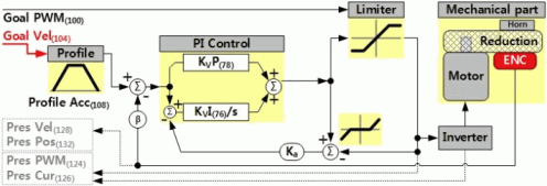
- Velocity I/P Gain
- Position D/I/P Gain, Feedforward Acceleration/Velocity Gain
- Bus Watchdog
- Goal PWM
- Goal Current
- Goal Velocity
- Profile Acceleration
- Profile Velocity
- Goal Position
- Realtime Tick
- Moving
- Moving Status
- Present PWM
- Present Current
- Present Velocity
- Present Position
- Velocity Trajectory
- Position Trajectory
- Present Input Voltage
- Present Temperature
- Indirect Address/Data
- 各アイテム詳細
適用  [1]
[1]
DynamixelプロトコルV2版ファームウェア Ver.40以降を搭載した以下のDynamixelに共通するコントロールテーブルです。
アイテム一覧  [5]
[5]
| Address | Item | Access | Default Value | Type/Range |
| 0 | Model Number | R | - | uint16 |
| 1 | ||||
| 2 | Model Information | R | 0 | uint32 |
| 3 | ||||
| 4 | ||||
| 5 | ||||
| 6 | Version of Firmware | R | ? | uint8 |
| 7 | ID | R/W (NVM) | 1 | uint8 0~252 |
| 8 | Baudrate | R/W (NVM) | 1 | uint8 0~7 |
| 9 | Return Delay Time | R/W (NVM) | 250 | uint8 0~254 |
| 10 | Drive Mode | R/W (NVM) | 0 | uint8 0~255 |
| 11 | Operating Mode | R/W (NVM) | 3 | uint8 0~16 |
| 12 | Secondary(Shadow) ID | R/W (NVM) | 255 | uint8 0~255 |
| 13 | Protocol Version | R/W (NVM) | 2 | uint8 1~2 |
| 14 ~ 19 | (reserve) | R | - | uint8 |
| 20 | Homing Offset | R/W (NVM) | 0 | int32 -1044479~1044479 |
| 21 | ||||
| 22 | ||||
| 23 | ||||
| 24 | Moving Threshold | R/W (NVM) | 10 | uint32 0~1023 |
| 25 | ||||
| 26 | ||||
| 27 | ||||
| 28 ~ 30 | (reserve) | R | - | uint8 |
| 31 | Temperature Limit | R/W (NVM) | 80 | uint8 0~100 |
| 32 | Max Voltage Limit | R/W (NVM) | 160 | uint16 95~160 |
| 33 | ||||
| 34 | Min Voltage Limit | R/W (NVM) | 95 | uint16 95~160 |
| 35 | ||||
| 36 | PWM Limit | R/W (NVM) | 885 | uint16 0~885 |
| 37 | ||||
| 38 | Current Limit | R/W (NVM) | 1194:MX-64 2047:MX-106 | uint16 0~1193:MX-64 0~2047:MX-106 |
| 39 | ||||
| 40 | Acceleration Limit | R/W (NVM) | 32767 | uint32 0~32767 |
| 41 | ||||
| 42 | ||||
| 43 | ||||
| 44 | Velocity Limit | R/W (NVM) | 380:MX-28 435:MX-64 360:MX-106 | uint32 0~1023 |
| 45 | ||||
| 46 | ||||
| 47 | ||||
| 48 | Max Position Limit | R/W (NVM) | 4095 | uint32 0~4095 |
| 49 | ||||
| 50 | ||||
| 51 | ||||
| 52 | Min Position Limit | R/W (NVM) | 0 | uint32 0~4095 |
| 53 | ||||
| 54 | ||||
| 55 | ||||
| 56 ~ 62 | (reserve) | R | - | uint8 |
| 63 | Shutdown | R/W (NVM) | 52(0x34) | uint8 0~63 |
| 64 | Torque Enable | R/W | 0 | uint8 0~1 |
| 65 | LED | R/W | 0 | uint8 0~1 |
| 68 | Status Return Level | R/W | 2 | uint8 0~2 |
| 69 | Registered Instruction | R | 0 | uint8 |
| 70 | Hardware Error Status | R | 0 | uint8 |
| 76 | Velocity I Gain | R/W | 1920 | uint16 0~32767 |
| 77 | ||||
| 78 | Velocity P Gain | R/W | 100 | uint16 0~32767 |
| 79 | ||||
| 80 | Position D Gain | R/W | 0 | uint16 0~32767 |
| 81 | ||||
| 82 | Position I Gain | R/W | 0 | uint16 0~32767 |
| 82 | ||||
| 84 | Position P Gain | R/W | 850 | uint16 0~32767 |
| 85 | ||||
| 88 | Feedforward Acceleration Gain | R/W | 0 | uint16 0~32767 |
| 89 | ||||
| 90 | Feedforward Velocity Gain | R/W | 0 | uint16 0~32767 |
| 91 | ||||
| 98 | Bus Watchdog | R/W | 0 | int8 -1~127 |
| 100 | Goal PWM | R/W | - | int16 -PWM Limit~PWM Limit |
| 101 | ||||
| 102 | Goal Current | R/W | - | int16 -Current Limit~Current Limit |
| 103 | ||||
| 104 | Goal Velocity | R/W | - | int32 -Velocity Limit~Velocity Limit |
| 105 | ||||
| 106 | ||||
| 107 | ||||
| 108 | Profile Acceleration | R/W | 0 | uint32 0~Acceleration Limit |
| 109 | ||||
| 110 | ||||
| 111 | ||||
| 112 | Profile Velocity | R/W | 0 | uint32 0~Velocity Limit |
| 113 | ||||
| 114 | ||||
| 115 | ||||
| 116 | Goal Position | R/W | - | int32 Min Position Limit~Max Position Limit -1048575~1048575 |
| 117 | ||||
| 118 | ||||
| 119 | ||||
| 120 | Realtime Tick | R | - | uint16 |
| 121 | ||||
| 122 | Moving | R | 0 | uint8 |
| 123 | Moving Status | R | 0 | uint8 |
| 124 | Present PWM | R | - | int16 |
| 125 | ||||
| 126 | Present Current | R | - | int16 |
| 127 | ||||
| 128 | Present Velocity | R | - | int32 |
| 129 | ||||
| 130 | ||||
| 131 | ||||
| 132 | Present Position | R | - | int32 |
| 133 | ||||
| 134 | ||||
| 135 | ||||
| 136 | Velocity Trajectory | R | - | |
| 137 | ||||
| 138 | ||||
| 139 | ||||
| 140 | Position Trajectory | R | - | |
| 141 | ||||
| 142 | ||||
| 143 | ||||
| 144 | Present Input Voltage | R | - | uint16 |
| 145 | ||||
| 146 | Present Temperature | R | - | uint8 |
| 147 ~ 167 | (reserve) | R | - | uint8 |
| 168 | Indirect Address 1 | R/W | 224 | uint16 64~661 |
| 169 | ||||
| 170 | Indirect Address 2 | 225 | ||
| 171 | ||||
| 172,173 ~ 218,219 | Indirect Address 3 ~ Indirect Address 26 | 226 ~ 249 | ||
| 220 | Indirect Address 27 | 250 | ||
| 221 | ||||
| 222 | Indirect Address 28 | 251 | ||
| 223 | ||||
| 224 | Indirect Data 1 | R/W | 0 | uint8 |
| 225 | Indirect Data 2 | |||
| 226 | Indirect Data 3 | |||
| 227 ~ 248 | Indirect Data 4 ~ Indirect Data 25 | |||
| 249 | Indirect Data 26 | |||
| 250 | Indirect Data 27 | |||
| 251 | Indirect Data 28 | |||
| 252 ~ 577 | (reserve) | R | - | uint8 |
| 578 | Indirect Address 29 | R/W | 634 | uint16 64~661 |
| 579 | ||||
| 580 | Indirect Address 30 | 635 | ||
| 581 | ||||
| 582,583 ~ 628,629 | Indirect Address 31 ~ Indirect Address 54 | 636 ~ 659 | ||
| 630 | Indirect Address 55 | 660 | ||
| 631 | ||||
| 632 | Indirect Address 56 | 661 | ||
| 633 | ||||
| 634 | Indirect Data 29 | R/W | 0 | uint8 |
| 635 | Indirect Data 30 | |||
| 636 ~ 659 | Indirect Data 31 ~ Indirect Data 54 | |||
| 660 | Indirect Data 55 | |||
| 661 | Indirect Data 56 |
- データ幅が16bitないし32bitのアイテムはリトルエンディアン(データの下位バイトから順に格納)。
- Accessに(NVM)とあるアイテムは不揮発メモリとなっており、電源を切っても値が保持される。また頻繁な書き換えは想定されていないため、書き換えは必要最低限にとどめること。
- Accessに(NVM)とあるアイテムとIndirect Addressを変更する場合は、Torque Enalbeが0でなくてはならない。
- (reserve)はシステムで予約され、読み出した値に有効性はない。また、書き込みを行ってはならない。
- Default Valueは出荷時ないしファクトリーリセットを行った際の値。又、ファームウェアのバージョンによって値が変更される場合がある。
各アイテム詳細  [6]
[6]
Model Number/Model Information  [7]
[7]
本品固有の値を保持します。異なる種類のDynamixelを混在して使用する際の個体識別などに使用できます。
| Model Name | Value |
| MX-28 | 30(0x1E) |
| MX-64 | 311(0x137) |
| MX-106 | 321(0x141) |
Version of Firmware  [8]
[8]
内蔵されるCPUに書き込まれたプログラムのバージョンです。ファームウェアの更新を行った際に合わせて自動的に変更されます。
ID  [9]
[9]
各Dynamixelを特定するための固有の値で0~252の範囲の数値で設定します。同一ネットワーク内に存在するDynamixelには各々異なるIDが要求されます。
Baudrate  [10]
[10]
通信する際のボーレートです。ホストDynamixelのボーレートは一致させなくてはなりません。
| Value | Baudrate [bps] |
| 0 | 9600 |
| 1 | 57600 |
| 2 | 115200 |
| 3 | 1000000 |
| 4 | 2000000 |
| 5 | 3000000 |
| 6 | 4000000 |
| 7 | 4500000 |
Return Delay Time  [11]
[11]
インストラクションパケットが送られた後、ステータスパケットを返すまでの待ち時間を設定します。
ホストにおいて半二重のバス制御のタイミングに合わせて調整しますが、弊社が提供するUSBシリアルI/Fを使用する限りでは0を設定しても問題ありません。
Delay Time [us] = Value * 2
Drive Mode  [12]
[12]
ホーンの回転方向やデュアルモードにおけるマスター/スレーブを設定します。
リバースモードはPosition, Velocity, PWMの各指令によるホーンの回転方向が変化します。
デュアルモードは2台のDynamixelを同期させて使用する際に一方をマスター、もう一方をスレーブに設定します。※MX-106のみ装備
| Bit | Name | Description |
| 7 | 常時0 | |
| 6 | 常時0 | |
| 5 | 常時0 | |
| 4 | 常時0 | |
| 3 | 常時0 | |
| 2 | 常時0 | |
| 1 | デュアルモード | 0:マスター 1:スレーブ ※MX-106のみ |
| 0 | リバースモード | 0:通常 (CCW方向を+、CW方向を-) 1:反転 (CCW方向を-、CW方向を+) |
デュアルモードを使用する際は、マスターとスレーブに設定されたDynamixelのDual Joint Connector同士をデュアルジョイントケーブルで接続します。スレーブに設定されたDynamixelはDual Joint Connectorから入力される信号でのみ動作し、ケーブルの配線方法によりスレーブの回転方向を決定します。
| Dual Mode | |
| Normal | Reverse |
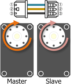 | 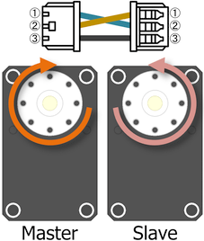 |
Operating Mode  [13]
[13]
動作モードを選択します。Valueに記載が無い値は予約済みのため、指定してはなりません。
なお、MX-28は電流センサを備えていないため、設定可能なモードが限られます。
| Value | Mode | Description |
| 0 | Current Control Mode | 電流制御。位置及び速度制御は行わない。 MX-28は指定不可 |
| 1 | Velocity Control Mode | 速度制御。位置及びトルク制御は行わない。 |
| 3 | Position Control Mode | 位置制御。GoalPositionは0~360°の1回転分の制御範囲に制限。 |
| 4 | Extended Position Control Mode | 拡張位置制御。GoalPositionの範囲が拡大され、最大±256回転まで対応。 |
| 5 | Current-Base Position Control Mode | 電流制限付き位置制御。GoalPositionの範囲が拡大され、最大±256回転まで対応。 MX-28は指定不可 |
| 16 | PWM Control Mode | PWMのデューティー比を制御。 |
Secondary(Shadow) ID  [14]
[14]
DynamixelのSecondary IDを設定します。Secondary IDは、IDと同様に各Dynamixelを識別するために用いられます。なお、Secondary IDに253以上の値が設定されている場合、Secondary IDは機能しません。
Protocol Version  [15]
[15]
Dynamixelプロトコルのバージョンを選択します。他のシリーズのDynamixelと混在させて使用する際はそのプロトコルのバージョンに合わせますが、異なるプロトコルを混在させて使用する事はできません。
| Value | Protocol Version | Description |
| 1 | 1.0 | AX, DX, RX, MX, EXシリーズと互換 |
| 2 | 2.0 | X, PROシリーズと互換 |
Homing Offset  [16]
[16]
この値が真の現在位置に加算されPresent Positionに反映されます。オフセット位置をホスト側では無くDynamixel側に持たせる際に使用します。
Position [deg] = Value * 360 [degC] / 4096
Moving Threshold  [17]
[17]
Present Velocityの絶対値とこの値を比較した結果がMovingに示されます。
Velocity [rpm] = Value * 0.229 [rpm]
Temperature Limit  [18]
[18]
Present Temperatureがこの値を超えるとHardware Error Statusの該当ビットがONになり、Shutdownで指定された動作に遷移します。
Temperature [degC] = Value * 1 [degC]
Max/Min Voltage Limit  [19]
[19]
Present Input Voltageがこの値の範囲を超えるとHardware Error Statusの該当ビットはONになり、Shutdownで指定された動作に遷移します。
Voltage [V] = Value * 0.1 [V]
Current Limit  [21]
[21]
Goal Currentの絶対値はこの値以下に制限されます。
MX-28ではreserveとなります。
Current [mA] = Value * 2.69 [mA]
Acceleration Limit  [22]
[22]
Profile Accelerationはこの値以下に制限されます。
Acceleration [rpm²] = Value * 214.577 [rpm²]
Velocity Limit  [23]
[23]
Goal Velocityの絶対値とProfile Velocityはこの値以下に制限されます。
Velocity [rpm] = Value * 0.229 [rpm]
Max/Min Position Limit  [24]
[24]
Operating ModeにPosition Control Modeが設定されている時にGoal Positionはこの値の範囲内に制限されます。
Position [deg] = Value * 360 [deg] / 4096
Shutdown  [25]
[25]
この設定とHardware Error Statusの論理積が0以外になると、Torque Enableは0になりモータの出力が遮断されシャットダウン状態に遷移します。以後通常のインストラクションパケットにてTorque Enableを1にする事ができません。
| Bit | Name |
| 7 | 常時0 |
| 6 | 常時0 |
| 5 | Overload Error |
| 4 | Electrical Shock Error |
| 3 | Motor Encoder Error |
| 2 | Overheating Error |
| 1 | 常時0 |
| 0 | Input Voltage Error |
なお、シャットダウン状態から復帰するには発生している障害を排除した後、電源の再投入か、REBOOTインストラクションパケットを受信しなくてはなりません。
Torque Enable  [26]
[26]
出力軸をフリーにするか、設定されたOperating Modeに従った制御を開始します。
| Value | Description |
| 0 | 出力軸フリー、制御停止、ロックされたアイテムを解除 |
| 1 | Operating Modeに従った制御開始、NVM及びIndirect Address領域のアイテムロック |
Status Return Level  [28]
[28]
ステータスパケットを返信するインストラクションパケットを選択します。
| Value | Instruction to respond |
| 0 | Ping |
| 1 | Ping, Read |
| 2 | Ping, Read, Write, Reg Write, Factory Reset, Reboot, Sync Read, Bulk Read |
Registered Instruction  [29]
[29]
Reg Writeインストラクションパケットを受信すると1、その後Actionインストラクションパケットを受信すると0になります。
Hardware Error Status  [30]
[30]
様々なフィードバックと内部の制御状態を比較した結果を示します。さらに、この値とShutdownの論理積の結果により動作を継続するか否かを決定します。
| Bit | Name | Description |
| 7 | - | 常時0 |
| 6 | - | 常時0 |
| 5 | Overload Error | 最大出力で制御できない負荷が継続的に発生した |
| 4 | Electrical Shock Error | 電気的に回路が衝撃を受けたり入力電力が不足してモータが正常動作しない |
| 3 | Motor Encoder Error | エンコーダが正常動作しない |
| 2 | Overheating Error | Present TemperatureがTemperature Limitを超えた |
| 1 | - | 常時0 |
| 0 | Input Voltage Error | Present VoltageがMax/Min Voltage Limitの範囲を超えた |
Velocity I/P Gain  [31]
[31]
速度制御演算における各種制御ゲインを指定します。
Operating ModeにVelocity Control Modeが設定されている時に有効です。
なお、制御ブロック中の各ゲインは、次の算式で示す減じられた値が用いられます。
KvI = (Velocity I Gain) / 65536
KvP = (Velocity P Gain) / 128
Position D/I/P Gain, Feedforward Acceleration/Velocity Gain  [33]
[33]
位置制御演算における各種制御ゲインを指定します。
Operating ModeにPosition Control Mode・Extended Position Control Mode・Current-Base Position Control Modeが設定されている時に有効な値です。
なお、制御ブロック中の各ゲインは、次の算式で示す減じられた値が用いられます。
KpD = (Position I Gain) / 16
KpI = (Position I Gain) / 65536
KpP = (Position P Gain) / 128
Bus Watchdog  [36]
[36]
無通信状態を監視する時間を指定します。
Bus Watchdogが1以上でかつTorque Enableが1である場合、ホストコントローラとDynamixel間の通信間隔を監視します。その間隔が指定時間よりも大きい場合にDynamixelは停止し、Bus Watchdogは-1に変更されます。Bus Watchdog Error状態になると、Goal PWM・Goal Current・Goal Velocity・Goal Positionの各アイテムは読み取り専用に変更されます。Bus Wathdogの値を0に変更すると、Bus Watchdog Errorは解除されます。
| Value | Description |
| 0 | Bus Watchdog無効, Bus Watchdog Error状態を解除 |
| 1~127 | Bus Watchdog有効 (Value * 20[ms]) |
| -1 | Bus Watchdog Error状態 |
Goal PWM  [37]
[37]
PWMのデューティー比を指定します。
Operating ModeにPWM Modeが設定されている事はもとより、全てのModeにおける制御演算結果はPWMのデューティ比として算出されるため、必ず制御の最終段においてこの値以下にデューティー比が制限されモータへ印加されます。
Duty [%] = Value * 100 [%] / 855
Goal Current  [38]
[38]
電流制御の目標値を指定します。
Operating ModeにCurrent Control ModeもしくはCurrent-Base Position Control Modeが設定されている時に有効な値で、Current-Base Position Control Mode時はPosition D/I/P Gain, Feedforward 2nd/1st Gainに示すブロック図に従って制御されます。
Current [mA] = Value * 2.69 [mA]
Goal Velocity  [39]
[39]
速度制御の目標値を指定します。
Operating ModeにVelocity Control Modeが設定されている時に有効な値で、Velocity I/P Gaiに示すブロック図に従って制御されます。
Velocity [rpm] = Value * 0.229
Profile Acceleration  [40]
[40]
Profileの加速度を指定します。
Operating ModeがCurrent Control Modeである時を除くModeに有効です。
Acceleration [rpm²] = Value * 214.577 [rpm²]
詳細はProfile Velocityを参照ください。
Profile Velocity  [41]
[41]
Profileの最大速度を指定します。
Operating ModeがCurrent Control ModeないしVelocity Control Modeである時を除くModeに有効です。なお、Velocity Control Mode時はGoal Velocityが最大速度として採用されます。
Velocity [rpm] = Value * 0.229 [rpm]
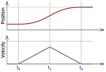
加速度・最大速度・目標位置の値によって最終的に4種類の軌跡が得られます。位置制御時における設定値による位置と速度のProfileを以下に示します。
| Profile | Condition, Waveform |
| ステップ | Velocity = 0, Acceleration = don't care |
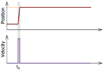 | |
| 矩形 | Velocity ≠ 0, Acceleration = 0 |
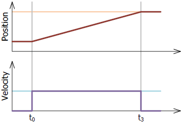 | |
| 三角 | Velocity ≠ 0, Acceleration ≠ 0 |
 | |
| 台形 | Velocity ≠ 0, Acceleration ≠ 0 |
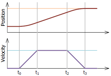 |
適当な加速度と最大速度を設定した上で目標位置を指令する事で、急峻な加速度を伴う位置決め制御による機械的なショックを軽減できます。また、目標位置への到達時間が決まっている場合は、時間から加速度と最大速度を求めて設定する事で対応できます。
なお、上記波形のt1及びt2は、概ね以下の数式で求められます。
t1 [ms] = 64 * (Profile Velocity) / (Profile Acceleration)
もしくは
t1 [ms] = 64 * (Goal Velocity) / (Profile Acceleration)

t2 [ms] = 64 * Δ(Present Position) / (Profile Velocity)
また、これらの他に急峻な加速度変化を抑える制御を行っているため、最終的な目標到達時間はt3よりも長くなる場合があります。
Goal Position  [42]
[42]
位置制御の目標値を指定します。
Operating ModeにPosition Control Mode・Extended Position Control Mode・Current-Base Position Control Modeが設定されている時に有効で、各Mode毎に指摘できる数値範囲が異なります。
| Operating Mode | Value Range | Max Turnover Number |
| 3 | Min Position Limit~Max Position Limit | 1 |
| 4 | -1048575~+1048575 | -256~+256 |
| 5 |
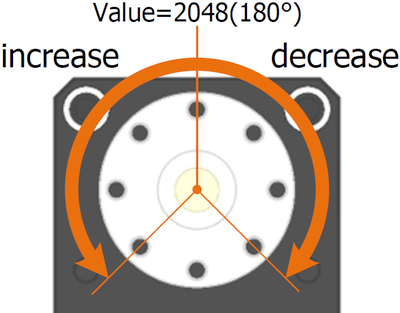
Position [deg] = Value * 360 / 4096
Realtime Tick  [43]
[43]
15ビットのフリーランカウンタで、1ms周期毎にインクリメントされます。
Moving  [44]
[44]
Present Velocityの絶対値とMoving Thresholdの比較結果を示します。
| Value | Description |
| 0 | Moving Threshold ≥ |Present Velocity| |
| 1 | Moving Threshold < |Present Velocity| もしくはProfileが進行中 |
Moving Status  [45]
[45]
動作中の状況を示します。
| Bit | Name | Description |
| 7 | - | 常時0 |
| 6 | - | 常時0 |
| 5 | Profile Type | 11:台形速度Profile 10:三角速度Profile 01:矩形速度Profile 00:Step速度Profile |
| 4 | ||
| 3 | Following Error | 位置制御時、位置がProfileに非追従 |
| 2 | - | 常時0 |
| 1 | Profile Ongoing | Goal Positionに基づくProfile進行中 |
| 0 | In-Position | 位置制御時、目標位置到達 |
Present Position  [49]
[49]
真の位置からHoming Offsetを除した出力軸の位置です。
Torque Enableが0の状態ではレンジフローするまで回転に応じた増減をしますが、Torque Enableを1にした瞬間にOperating Modeに依存した値でクリップされます。
Position [deg] = Value * 360 [deg] / 4096
Velocity Trajectory  [50]
[50]
Profileによって生成された目標速度を逐次示します。
Operating ModeにVelocity Control Mode・Position Control Mode・Extended Position Control Mode・Current-Base Position Control Modeが設定されている時に有効です。
Position Trajectory  [51]
[51]
Profileによって生成された目標位置を逐次示します。
Operating ModeにPosition Control Mode・Extended Position Control Mode・Current-Base Position Control Modeが設定されている時に有効です。
Indirect Address/Data  [54]
[54]
コントロールテーブル上のアドレスを再構成します。
Indirect Address N(N=1~56)とIndirect Data N(N=1~56)は対になっており、Indirect Address Nに任意のコントロールテーブル上のアドレスXを設定すると、その後Indirect Data Nへアクセスする事はIndirect Address Nに設定されたアドレスXへ間接的にアクセスする事になります。
具体的な例として、ホストから頻繁にアクセスしたいアイテムが複数あり、それらが離れたアドレスに配置されていた場合を考えます。通常はそれらアイテム全てをまたぐアドレス範囲のデータをまとめてアクセスするか、個々のアイテムに個別にアクセスするとった手段を執ります。これには本来無用なデータやアクセス回数が強いられるため、通信のトラフィックが上がる要因になるのと、ホスト側のプログラムの負担になります。
ホストから書き込み対象としてPosition P Gain・Goal Velocity・Goal Position、読み出し対象としてPresent Position・Present Temperatureがあった場合、これらをIndirect Data領域に再配置するには以下の手順を踏みます。
- Position P Gainのアドレス84~85をIndirect Address 1~2に書き込み
- Goal Velocityのアドレス104~107をIndirect Address 3~6に書き込み
- Goal Positionのアドレス116~119をIndirect Address 7~10に書き込み
- Present Positionのアドレス132~135をIndirect Address 11~14に書き込み
- Present Temperatureのアドレス146~147をIndirect Address 15~16に書き込み
以後Indirect Data 1からの連続した224番地にアクセスする事は、再配置したアイテムへ個々に間接的にアクセスした事になります。
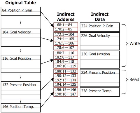
なお、Indirect Addressがデフォルト値のままであれば、Indirect Data領域はユーザ任意のRAM領域として扱うことができます。
Links list
(This host) = https://www.besttechnology.co.jp
- (This host)/modules/knowledge/?MX%20Series%20Control%20table%282.0%29#v0412e2a
- (This host)/modules/knowledge/?Dynamixel%20MX-28
- (This host)/modules/knowledge/?Dynamixel%20MX-64
- (This host)/modules/knowledge/?Dynamixel%20MX-106
- (This host)/modules/knowledge/?MX%20Series%20Control%20table%282.0%29#q28d55a1
- (This host)/modules/knowledge/?MX%20Series%20Control%20table%282.0%29#uabd4e49
- (This host)/modules/knowledge/?MX%20Series%20Control%20table%282.0%29#f8895243
- (This host)/modules/knowledge/?MX%20Series%20Control%20table%282.0%29#jc5551fd
- (This host)/modules/knowledge/?MX%20Series%20Control%20table%282.0%29#u1feceb7
- (This host)/modules/knowledge/?MX%20Series%20Control%20table%282.0%29#gd2e9bfc
- (This host)/modules/knowledge/?MX%20Series%20Control%20table%282.0%29#b77cfd17
- (This host)/modules/knowledge/?MX%20Series%20Control%20table%282.0%29#pd498215
- (This host)/modules/knowledge/?MX%20Series%20Control%20table%282.0%29#j5c7292f
- (This host)/modules/knowledge/?MX%20Series%20Control%20table%282.0%29#i3a9c5b3
- (This host)/modules/knowledge/?MX%20Series%20Control%20table%282.0%29#g1a9fe0a
- (This host)/modules/knowledge/?MX%20Series%20Control%20table%282.0%29#kfeaa64e
- (This host)/modules/knowledge/?MX%20Series%20Control%20table%282.0%29#z8cfaf32
- (This host)/modules/knowledge/?MX%20Series%20Control%20table%282.0%29#uad86a63
- (This host)/modules/knowledge/?MX%20Series%20Control%20table%282.0%29#d7f96189
- (This host)/modules/knowledge/?MX%20Series%20Control%20table%282.0%29#wef400f2
- (This host)/modules/knowledge/?MX%20Series%20Control%20table%282.0%29#y2cc93fd
- (This host)/modules/knowledge/?MX%20Series%20Control%20table%282.0%29#n0dd90ae
- (This host)/modules/knowledge/?MX%20Series%20Control%20table%282.0%29#n6a5f754
- (This host)/modules/knowledge/?MX%20Series%20Control%20table%282.0%29#l737bbef
- (This host)/modules/knowledge/?MX%20Series%20Control%20table%282.0%29#vbc701c4
- (This host)/modules/knowledge/?MX%20Series%20Control%20table%282.0%29#wfdacf65
- (This host)/modules/knowledge/?MX%20Series%20Control%20table%282.0%29#h4e1230d
- (This host)/modules/knowledge/?MX%20Series%20Control%20table%282.0%29#r63d9af2
- (This host)/modules/knowledge/?MX%20Series%20Control%20table%282.0%29#t7805606
- (This host)/modules/knowledge/?MX%20Series%20Control%20table%282.0%29#u710d2bc
- (This host)/modules/knowledge/?MX%20Series%20Control%20table%282.0%29#n3099aee
- (This host)/modules/knowledge/gate.php?way=ref&_nodos&_noumb&page=X%20Series%20Control%20table&src=DX_CtrlBlock%28Velocity%29.png
- (This host)/modules/knowledge/?MX%20Series%20Control%20table%282.0%29#d0c6ac0c
- (This host)/modules/knowledge/gate.php?way=ref&_nodos&_noumb&page=X%20Series%20Control%20table&src=DX_CtrlBlock%28Position%29.png
- (This host)/modules/knowledge/gate.php?way=ref&_nodos&_noumb&page=X%20Series%20Control%20table&src=DX_CtrlBlock%28Cur%26Pos%29.png
- (This host)/modules/knowledge/?MX%20Series%20Control%20table%282.0%29#v345fcb0
- (This host)/modules/knowledge/?MX%20Series%20Control%20table%282.0%29#x7993b36
- (This host)/modules/knowledge/?MX%20Series%20Control%20table%282.0%29#h25c5adf
- (This host)/modules/knowledge/?MX%20Series%20Control%20table%282.0%29#x7810cd9
- (This host)/modules/knowledge/?MX%20Series%20Control%20table%282.0%29#p37d042e
- (This host)/modules/knowledge/?MX%20Series%20Control%20table%282.0%29#k31e5f2f
- (This host)/modules/knowledge/?MX%20Series%20Control%20table%282.0%29#a86abf50
- (This host)/modules/knowledge/?MX%20Series%20Control%20table%282.0%29#q9936d2f
- (This host)/modules/knowledge/?MX%20Series%20Control%20table%282.0%29#q27c1167
- (This host)/modules/knowledge/?MX%20Series%20Control%20table%282.0%29#jf2ccbc3
- (This host)/modules/knowledge/?MX%20Series%20Control%20table%282.0%29#q60316d2
- (This host)/modules/knowledge/?MX%20Series%20Control%20table%282.0%29#x7fc73c2
- (This host)/modules/knowledge/?MX%20Series%20Control%20table%282.0%29#na7ab4d4
- (This host)/modules/knowledge/?MX%20Series%20Control%20table%282.0%29#rc31835f
- (This host)/modules/knowledge/?MX%20Series%20Control%20table%282.0%29#de194cd2
- (This host)/modules/knowledge/?MX%20Series%20Control%20table%282.0%29#w9f5f284
- (This host)/modules/knowledge/?MX%20Series%20Control%20table%282.0%29#y010f5f7
- (This host)/modules/knowledge/?MX%20Series%20Control%20table%282.0%29#h54b3728
- (This host)/modules/knowledge/?MX%20Series%20Control%20table%282.0%29#jaa405dd
![[PukiWiki] [PukiWiki]](https://www.besttechnology.co.jp/modules/knowledge/image/pukiwiki.png)
 [32]
[32]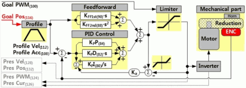 [34]
[34]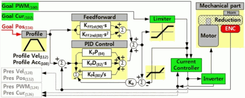 [35]
[35]